bi 191 u
philips
Restoration
bi 191 u
philips
Restoration
Let's begin the restoration of a Philips model… specifically, this small 1951 ‘kitchen’ radio is interesting due to some circuit solutions that make it unique. It is important to consider that Philips aimed to create a model with extremely low production costs. This model lacks a power transformer, has only 4 tubes instead of the usual 5 found in competing circuits, uses RimLock-base tubes, and can only be powered at 110V or 160V. We will later see that the design also included an optional resistor for operation at 220V. It is an AM-only radio but has remarkable selectivity, and in terms of quality, it is a typical Philips product from that era—very well built. Since there is no transformer, the filaments of the tubes are powered using 'U' tubes, which have high filament voltage requirements. By connecting all the filaments in series (along with a dial lamp), the total voltage matches the mains voltage. This way, the filaments are powered directly from the electrical grid!
Bakelite cabinet restoration
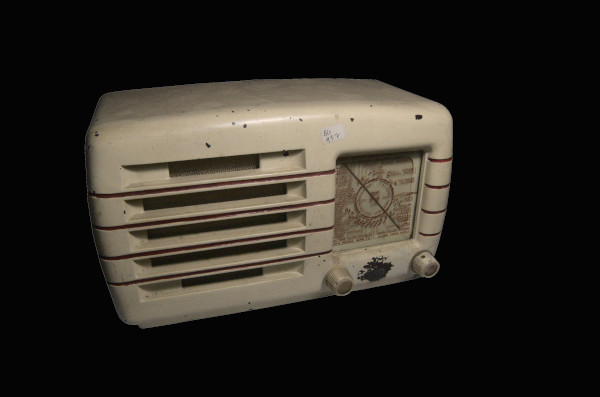
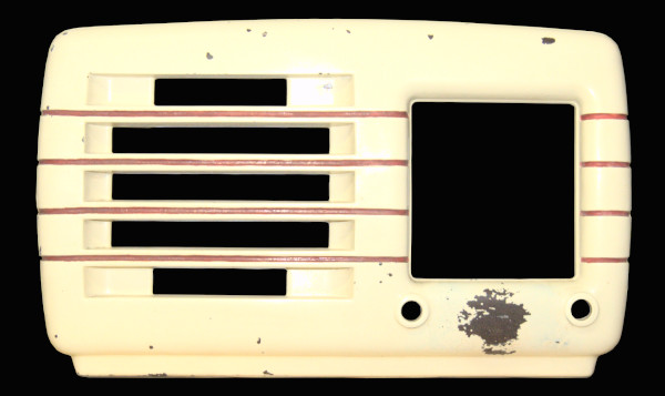
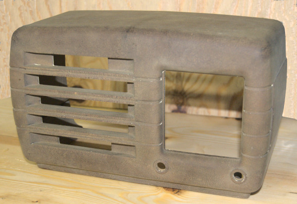
The cabinet of this model is made entirely of Bakelite. The condition of my unit is not disastrous; in fact, it has no chips, cracks, or missing parts. However, as visible in many areas, the original paint is worn or chipped, likely due to some impacts. The idea of simply cleaning it and leaving it ‘as is’ with its aged patina does not appeal to me because I prefer to restore the object to its original appearance, making it both functional and visually appealing. Who would want an object in their home that, although antique, shows such evident and unsightly signs of wear? Of course, if we were talking about a wooden piece of furniture, I would probably be the first to appreciate its ‘signs of time.’ However, in that case, it would be a handcrafted item, possibly one of a kind, making refinishing unnecessary. The cabinet of this radio, on the other hand, is mass-produced, made of plastic—so in my personal opinion, it’s an entirely different matter! Therefore, I proceed with a complete cleaning of the piece, stripping off the paint and restoring the Bakelite to its original state. On the side, you can see the result of the restoration. After a light sanding, I apply several coats of pearl white paint (RAL 1013) to bring it back to its original color. Finally, I apply multiple layers of protective clear coat.
,
The circuit diagram
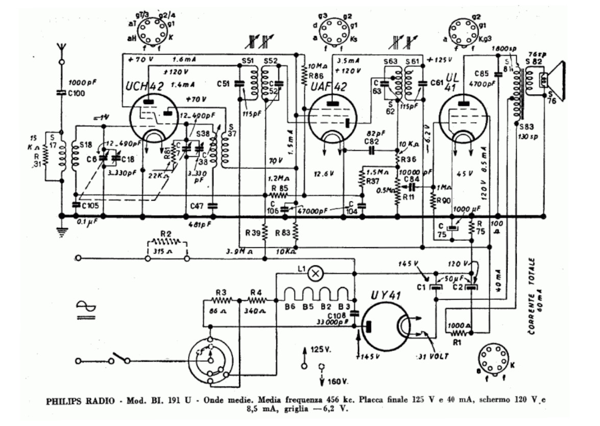
Let's now analyze the circuit diagram of this radio. As previously mentioned, all the tubes used are from the U series, meaning that the filament heating voltage is higher than usual. As we can see, one branch of the mains voltage is interrupted by the switch (integrated into the volume potentiometer) before entering the voltage selector, which essentially just inserts or removes resistor R3 (86Ω) from the power circuit. This acts as a voltage drop resistor when the 160V setting is selected. We also see that the schematic indicates the total circuit current as 60 mA, along with other very useful values for repairs at the bottom of the diagram.
The Power Supply!
In my opinion, it is important to fully understand what Philips designed for this radio. Many of these can still be found around, but since they operate at a voltage that is no longer common, they are either turned off or connected to a power transformer. There is almost no information available online about this, so, to help all enthusiasts, I will try to explain the circuit in a way that anyone can repair it and, if needed, easily convert it to 220V. Philips has already made this easier for us, as the radio was designed to support this voltage—once you understand how, you can eliminate the need for a transformer!
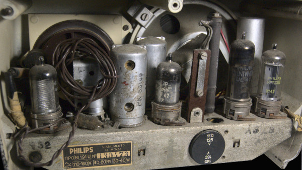
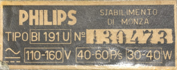
Let's start with the confirmed data. Here, I present a photograph of the nameplate of my unit.
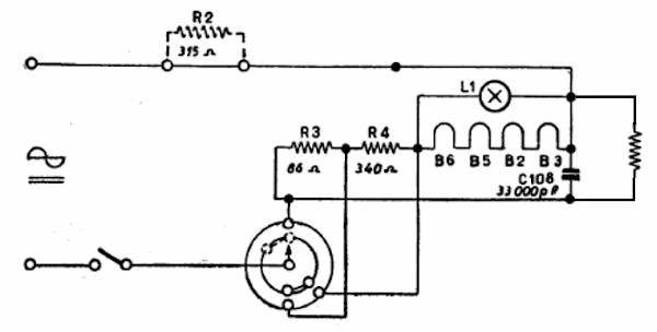
Here is the section related to the power supply. Now, we will refer only to this image, in which I have also removed the arrows indicating the positions for 160V and 125V, as they were misleading. The entire radio circuit has been replaced with the equivalent resistor you see on the far right, and to size it correctly, we will rely on the values provided by Philips.
The first consideration to make is that all resistors (and tubes) have fairly wide tolerances. So, even though we are about to perform some calculations, we must keep in mind that these tolerances will affect the values we obtain, both positively and negatively. Another important consideration is that, back in the day, circuit diagrams were often drawn by ‘young designers’ who copied the schematics calculated by ‘older, more experienced engineers.’ Therefore, it is not uncommon to find errors, inconsistencies, or incorrect data in these historical schematics.
Here, for example, we have a nameplate indicating 110V and 160V, but in the schematic, we find 125V and 160V, while on the radio, the values are doubled: 110/125V and 145/160V. The arrows are misleading because they suggest that if the arrow points to the upper contact, the circuit is set to 125V, while if it points downward, it is at 160V… but in reality, it’s the opposite. Then, on the right side of the schematic, we see the label ‘total current 60 mA’… but at what voltage? It is assumed to be 145V since this value is marked on the diode anode… but it’s not entirely clear! Another significant detail is the ‘jumper’ between the two lower pins of the voltage selector. In practice, this jumper effectively cancels out the 340Ω resistor! Finally, as previously mentioned, R2 is drawn with dashed lines because, in reality, it is not installed in the circuit. However, adding it will allow the radio to operate at 220V. Interestingly, Philips even created a designated space and mounting support for this resistor… Thank you, Philips!
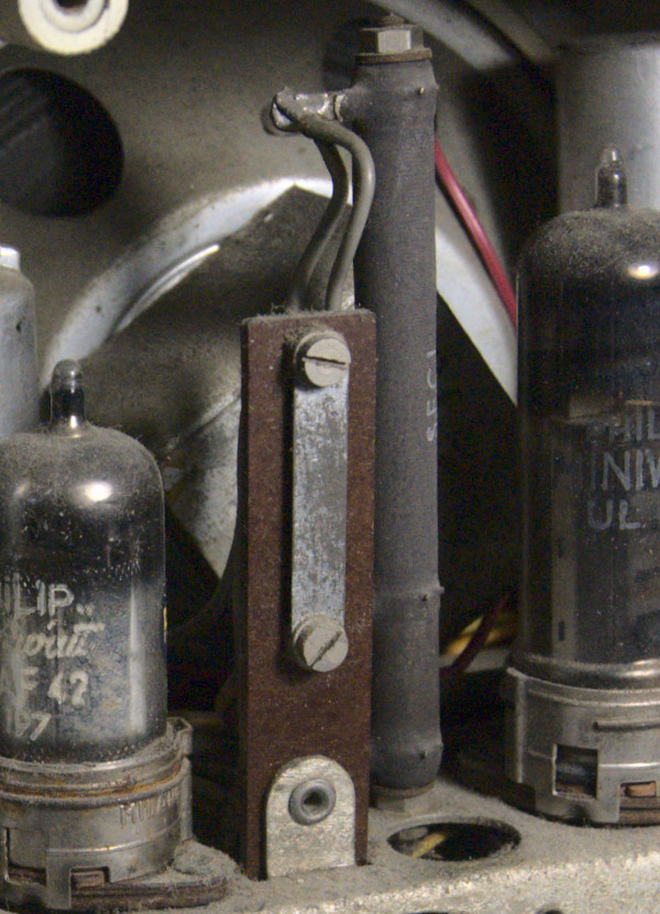
In the image, you can see a metal rod screwed onto an insulating support… well, that is the space for R2. By replacing the rod with the resistor, there won’t even be a need to wire it separately—a quick and easy job without a soldering iron! We will later see the correct way to proceed. Since we're here, the gray cylinder right behind it is a dual power resistor with three terminals: essentially, it consists of R3 and R4 in series, mounted as a single component. These three resistors all serve to adapt the selected voltage to the level needed for the circuit to operate. As a result, they must dissipate a lot of power (less for 110V and much more for 220V). For this reason, they are all high-wattage resistors and generate a significant amount of heat.
To calculate the equivalent resistance that represents the entire radio from the rectifier tube onward, we consider the data provided in the schematic: a voltage of 145V and a current draw of 60mA. Using these values, we calculate that the circuit has a total resistance of 2417Ω, a voltage drop of 145V, and a power consumption of 9 watts. Let’s keep these values in mind, as they define the EQ-R-Radio (Equivalent Resistance of the Radio).
110V Power Supply
Now, let's analyze each case one by one, and with a calculator in hand, we'll try to run some calculations using Ohm's law and the data we have available!
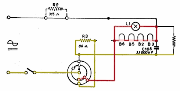
At 110 volts, the voltage selector will make contact at the lower position (as seen in the schematic). So, on one side, it will connect to the radio circuit (EQ-R-Radio) passing through R3 (yellow line in the photo), and on the other side, it will pass through all the filaments connected in series (red line). Now, things get a bit more complex... The filaments (B6, B5, B2, B3) have the following resistance values: 310Ω, 450Ω, 126Ω, and 140Ω, for a total of 1026Ω. That’s fine, but in parallel with the filaments, there is a 130V 5W lamp. We calculate its resistance as 3380Ω, with a current draw of 38mA. Since the lamp is in parallel with the filaments, their respective resistances (3380Ω and 1026Ω) result in an equivalent resistance of 787Ω. All the filaments must draw the same amount of current, which, according to the datasheet, is 100mA, plus the 38mA from the lamp. Thus, we have an equivalent resistance for the filaments + lamp of 787Ω, through which 138mA flows, causing a voltage drop of 109V, with a total power dissipation of 15 watts.
Looking closely at the schematic, we can see that the EQ-R-Radio is in series with R3, and this pair of resistors is in parallel with the filaments (and consequently with the lamp). Therefore, the series of R3 + EQ-R-Radio equals 2503Ω and draws 44mA, consuming 5 watts and dropping 110 volts. As we have already seen, the parallel combination of the filaments + L1 is 787Ω with a current consumption of 138mA, 15 watts, and a voltage drop of exactly 109V. Finally, the parallel combination of EQ-R-Radio + R3 with the filaments + lamp results in 599Ω with a current draw of 182mA and 20 watts, and the total voltage drop is, as expected, 110 volts... and the radio works!
We notice that at the set 110 volts, R4 is bypassed... and indeed, it does not appear in any of the calculations.


160V Power Supply
Okay… now let’s see what happens when we set the voltage selector to 160V. Keeping the previous calculations regarding the resistance values and all the reasoning about the parallel components, we see that the radio circuit is directly powered (red line). Before you start doubting and asking questions, let me clarify one thing: if you look at the table, you'll see that the radio circuit has a resistance of 2417Ω and a current draw of 66mA. But didn’t we say it was 60mA? Well, 60mA was the consumption at 145V. At that voltage, I calculated the resistance, which, when applied to the new 160V voltage, results in a consumption of 66mA. Moving on to the other branch, we see that in this case, both R3 and R4 are used, bringing the voltage to the parallel combination of the filaments + L1. In this case, the total resistance of the circuit is 808Ω with a current draw of 205mA, which results in 34 watts of power consumption and a voltage drop of 165V. (Keep an eye on the doubts... remember what we mentioned at the beginning? Consider the tolerance of the components, the mains voltage, etc...).
We immediately realize that the radio powered at 160V has a significantly higher anode voltage... and the entire circuit and polarization curves shift to a higher level, making better use of the tubes.

220V Power Supply
Now that we have analyzed and understood the 'standard', let’s look at the optional component... the R2 resistor! Why didn’t Philips install it? We could simply say it was a cost issue... but if that were the case, why spend money to create a support, wire it, and so on? No, I don’t believe the reason was cost: the design was for a radio that could work at various voltages, both AC and DC... and the resistors were installed based on the country in which the radio was sold. In 1951 (the year it was produced), there was a lot of confusion. After the war, many systems were destroyed, and each country/region supplied power independently... that’s all!
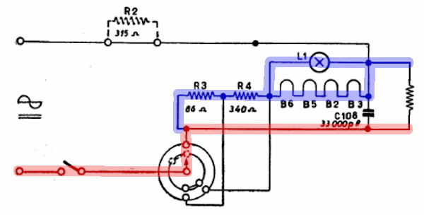
Now, why use a 220/110 transformer to power this radio and, moreover, make it operate with a low anode voltage? Simple... the radio hasn’t been studied, and the potential of this little gem hasn’t been understood! So... let’s unscrew the bridge, place the 315Ω resistor, and power it up at 220V. The voltage selector will be set to 160V to also use R3 and R4 in series, which will heat up, yes, but in the same way they heat up at 160V... they have been correctly calculated (and it’s about time!!). In the image, the green line highlights the path of the other branch of the mains voltage (which we hadn’t considered until now), and in the table just below, you can see the recalculated voltage, resistance, and current values for the new voltage. At this voltage, the radio consumes 49 watts... but in reality, the radio circuit stays at very low levels. In this case (as with the 160V), what significantly affects power consumption are the drop resistors, which dissipate a lot of energy as heat. It’s certainly not a class A radio... at least in terms of energy consumption!
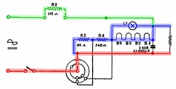

220V Power Supply with L1 burned
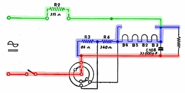

My unit mistakenly has a 5W 220V bulb installed, which would have a resistance of 9680Ω instead of the correct 3380Ω. Clearly, in this case, things shift a bit, and the filament circuit would have a resistance of 1767Ω, dropping 217V and drawing 123mA. In my opinion, it’s clear that it’s better to have a 220V bulb than nothing at all. From a functional standpoint, it’s even better than a 130V bulb. However, the purpose of the bulb is also another: when powered on, all the filaments are cold, and their resistance is very low, as is the bulb’s, which, in this case, offers a lower resistance and limits the current peak through the filaments. If we used a 220V bulb, this ‘protection’ would be partially lost, and we would be stressing all the filaments every time we turn it on. Therefore, in desperate cases, a 220V bulb may be used, but be aware that we’re shortening the lifespan of the filaments and that it will be necessary to get a 130V bulb!
I believe I have analyzed every aspect of the interesting power supply circuit of this small radio, and I hope to help many in its proper use or repair. I have never found any documentation online about this, and given the radio's popularity, I am sure that this part of my work will be appreciated by many: I look forward to receiving your emails with your comments!!
Now, let’s proceed with the restoration!!
Let's start the electrical restoration
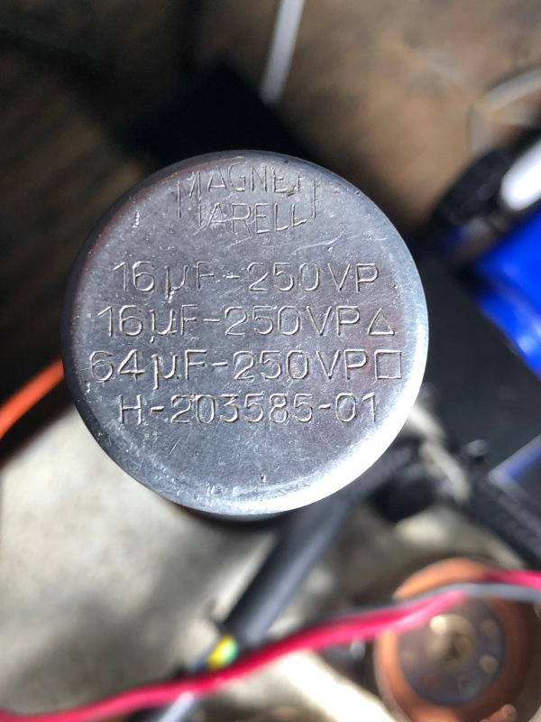
After analyzing the schematic, I start as usual with a comparative observation between the schematic and the device: I immediately notice that many 'hands' have been involved in this radio, and some repairs were not done as properly as they should have been. In the power supply section, I see that the bulb is 220V instead of 130V... some mounts are poorly soldered, and with the soldering iron, some capacitors were damaged, burning them. Some wires show melted insulation, probably due to previous repairs, and the filter capacitor values are much lower than required. In particular, which causes me quite a few problems, the vertical capacitor that should have been 50 + 50 uF was replaced with one rated 16 + 16 + 64 uF, and I believe subsequently, another 25 + 25 uF capacitor was added. The 1000 uF capacitor was replaced with a 500 uF one (on paper... but still in loss), and the ground reference for the primary of the transformer is soldered onto an unused pin of the rectifier tube (by itself!)... so the reference was missing. The absence of the 50 + 50 uF capacitor creates some problems because the internal space to fit two new capacitors is really limited, and removing the 16 + 16 + 64 uF capacitor causes an aesthetic issue (there would be a missing part!). I assume that this device was abandoned because it wasn’t working well—very low volume, buzzing, reception difficulties... before continuing with the analysis, I decide to reorder the power supply section!
I will not use anything from the triple capacitor, but I will keep it for aesthetic reasons. I will completely remove the 25 + 25 uF capacitor and install two 50 uF capacitors as per the schematic. The rectifier tube I found is a UY42 instead of a UY41; the two are practically equivalent.
One must not be misled by the schematic; the two 50uF filter capacitors have the positive side connected to the cathode of the rectifier and the negative side to the phase of the mains voltage. In my unit, the double 25 + 25 uF capacitor that should have replaced the two 50uF capacitors is, moreover, mounted the wrong way around. Another mistake I found in my radio is the 10K resistor R36, which is not connected in series with the potentiometer but on its wiper (along with the capacitor). Next, another mistake I found: the piece of wire functioning as an antenna, instead of being connected in series with the coil and the 15K resistor R31, is connected to the grid of the UCH42 (???). The last inconsistency I found, compared to the schematic, is on the output transformer, which, instead of being connected after the 1000Ω resistor R1, was connected to an unused pin of the UY41... and thus remained disconnected.
It is necessary to replace the two 47,000 pF capacitors (C106 and C104) as both are leaking.
Having restored everything and replaced the damaged UY41, the radio turned on, and I was able to explore the entire AM band, which, of course, is completely empty, except for the interference. I was able to tune into the Rai station, and I wonder, given the announcements from the beginning of the year (2022), if it hasn't been closed yet or if someone is re-broadcasting an FM channel on the Medium Waves. I will try the radio in the evening/night hours to check if it is possible to tune into distant foreign stations.
The result!
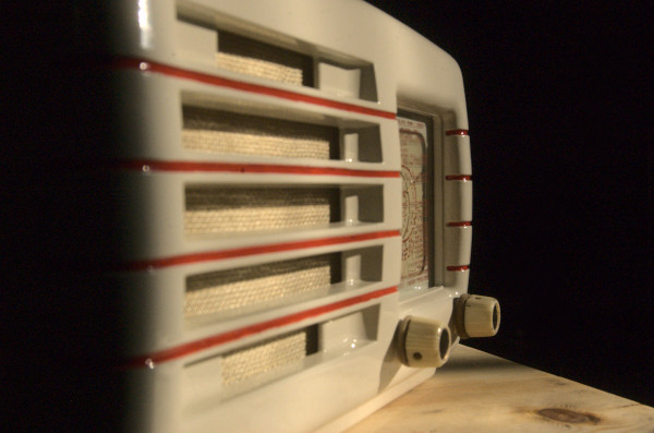
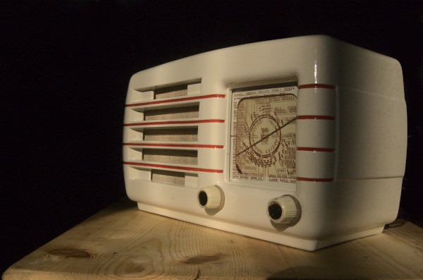
And here are some images of the final result. This small radio has a truly beautiful and modern design.
